How to Wire Model Train Layouts: A Complete Step-by-Step Guide
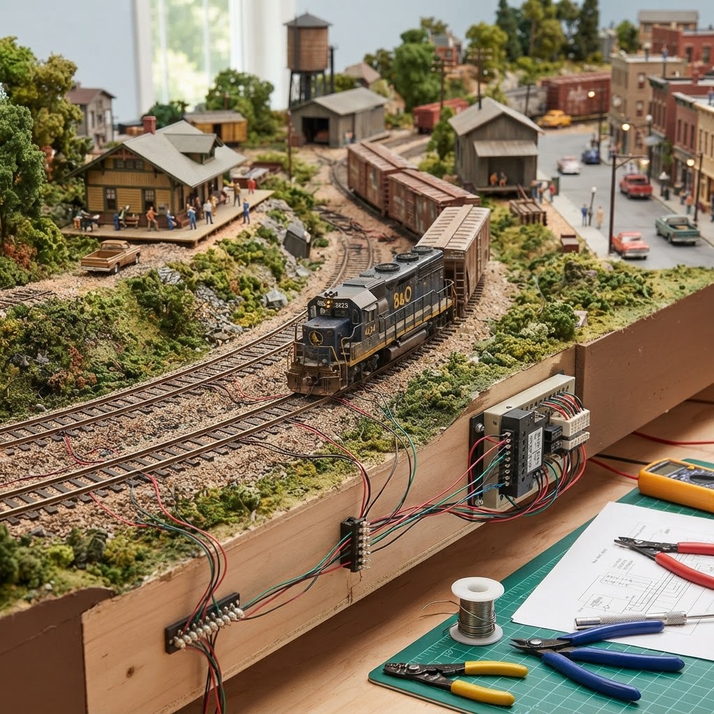
Learning how to wire model train layouts is one of the most rewarding — and occasionally frustrating — skills you'll develop as a model railroader. Whether you're just unboxing your first starter set or planning an ambitious multi-level layout, understanding the electrical fundamentals behind your railroad is what separates a static display from a living, breathing miniature world. Get the wiring right, and your trains will run smoothly for years. Get it wrong, and you'll be chasing mysterious short circuits and stalling locomotives for months.
The good news is that wiring a model train layout doesn't require an electrical engineering degree. With the right guidance, the correct tools, and a bit of patience, even complete beginners can wire a reliable, expandable layout. If you're brand new to the hobby, we recommend starting with The Ultimate Beginner Guide to Model Railroading: Start Your Journey Today before diving into this article — it'll give you the foundational context that makes everything here click.
In this comprehensive guide, we'll walk you through everything from basic DC wiring concepts to Digital Command Control (DCC) systems, bus wiring, block detection, turnout control, and troubleshooting. No matter what scale you're modeling or how complex your layout plans are, this guide will give you the knowledge and confidence to wire it properly.
Understanding the Basics: DC vs. DCC
Before you pull out a single wire, you need to make a fundamental decision: are you running DC (Direct Current) or DCC (Digital Command Control)? This choice shapes every wiring decision you'll make going forward.
DC Wiring: Simple and Affordable
Traditional DC layouts use variable voltage to control train speed — more voltage means faster trains. It's a proven system that's been used since the hobby began. DC wiring is simpler and less expensive upfront, which makes it appealing for beginners or those building smaller layouts.
The core concept is straightforward: your power pack sends current through two rails, and your locomotive's motor responds to that current. Reverse the polarity, and the train goes in the opposite direction.
However, DC has limitations. On a DC layout, every locomotive in a powered block responds to the same voltage signal. You can't independently control two trains in the same block — unless you divide your layout into separate electrical blocks, each with its own power source or toggle switch.
DCC Wiring: More Complex, More Capability
DCC sends a constant voltage through the rails while embedding digital commands in that signal. Each locomotive has a decoder chip that listens for its unique address. This means multiple trains can run independently on the same track, each with individual speed, direction, lighting, and sound control.
For a deeper comparison of these two systems, check out our detailed article on DCC vs DC: The Ultimate Guide to Choosing the Best Model Train Power System. If you've already decided to go DCC, our guide on The Best Way to Upgrade to DCC: A Beginner's Step-by-Step Guide will walk you through the process step by step.
Essential Wiring Tools and Materials
Having the right tools makes wiring your layout dramatically easier and safer. Here's what you'll need:
- Wire strippers and crimpers — essential for clean, reliable connections
- Soldering iron and solder — for permanent, low-resistance joints
- Multimeter — for testing voltage, continuity, and diagnosing problems
- Rail joiners (electrical and insulating) — for connecting and isolating track sections
- Terminal blocks or barrier strips — for organizing multiple wire connections
- Heat shrink tubing — for insulating soldered joints
- 18–22 AWG wire — for feeder wires; 14–16 AWG for bus wires on larger layouts
Color-coding your wires is not optional — it's a best practice. Use red for the positive (right) rail and black for the negative (left) rail consistently throughout your entire layout. This simple discipline will save you enormous troubleshooting headaches later.
Browse our recommended products page for a curated list of wiring tools and supplies suited to every scale and budget.
Planning Your Wiring Before You Build
The single biggest mistake new modelers make is building their layout first and wiring it later. Wiring is dramatically easier when it's planned from the beginning.
Draw a Wiring Diagram
Before laying a single piece of track, sketch out your wiring plan. Mark where your power feeds will connect, where block gaps will be cut, and where turnouts and accessories will sit. Even a rough hand-drawn diagram on paper is infinitely better than trying to remember it all in your head.
Decide on Block Wiring (DC) or Simplified Bus (DCC)
For DC layouts, plan your electrical blocks — sections of track that can be independently powered or isolated. Each block needs at least one power feed and insulated rail joiners at each end.
For DCC layouts, block wiring is less critical for operations, but power districts (sections of track protected by separate circuit breakers) are still highly recommended. They contain short circuits and protect your decoders.
Consider Your Scale and Layout Size
Larger scales and larger layouts need heavier wiring. An N scale switching layout and a large-scale garden railroad have vastly different electrical demands. If you're modeling in large scale, see our guide to Best DCC Systems for Large Scale Trains: A Comprehensive Guide for scale-specific wiring advice.
Wiring Your Track: Step-by-Step
Step 1: Lay Track and Plan Feed Points
Once your track plan is finalized, lay your track but don't permanently fix it until you've confirmed your electrical connections work. Identify where you'll solder feeder wires to the rails — ideally every 3–6 feet on larger layouts to prevent voltage drop.
Step 2: Install the Bus Wires
For any layout larger than a simple oval, run a main bus beneath the layout — two heavy-gauge wires (one per rail polarity) running the length of your layout. All feeder wires connect to this bus, which connects back to your power source. This "home run" approach ensures even power distribution and makes troubleshooting far easier.
Step 3: Solder Feeder Wires to the Rails
Using a fine-tipped soldering iron, solder short feeder wires (18–22 AWG) directly to the outside of the rail web — never the top of the rail where it would interfere with wheel contact. Work quickly to avoid melting ties or warping plastic track bases. Drill small holes through the benchwork near each feed point and route wires below the layout to your bus.
Step 4: Connect Feeders to the Bus
Strip the ends of your feeder wires and connect them to the corresponding bus wire — red feeders to the red bus, black feeders to the black bus. Use terminal blocks or solder and heat-shrink for solid connections. Never use wire nuts — they loosen with vibration over time.
Step 5: Test Before You Scenery
Before adding ballast, ground cover, or scenery, test every section of track with your multimeter and run a locomotive through the entire layout. Fix any dead spots or shorts now, while everything is still accessible.
Wiring Turnouts (Switches)
Turnouts introduce additional complexity because they have moving parts and electrical routing that varies by manufacturer and type.
Power Routing vs. Non-Power Routing Turnouts
Some turnouts (like many Peco models) route power only to the selected route — the diverging or straight path. Others pass power through all routes regardless of switch position. Understanding which type you have determines whether you need additional wiring for stub tracks and sidings.
Turnout Motor Wiring
Manually operated turnouts are the simplest — no wiring needed beyond the track itself. But motor-driven turnouts (solenoid or slow-motion) require power feeds and often a control panel with toggle switches or pushbuttons. Plan your control panel early and run wiring to turnout locations before scenery goes in.
Wiring for DCC: Key Considerations
If you've chosen DCC, your track wiring is simpler in some ways — no block isolation for train control — but there are still important considerations.
Choose the Right DCC System
Your DCC command station is the heart of your layout. For beginners and budget-conscious modelers, check out Best DCC Controller for Budget: Top Picks for Every Model Railroader. For a comprehensive overview of the best systems on the market, our 10 Best DCC Systems for Model Railroads: A Comprehensive Buyer Guide covers everything from entry-level to advanced command stations.
Install Power Districts and Circuit Breakers
Even on a DCC layout, divide your track into power districts with auto-reversing circuit breakers. If a locomotive derails and causes a short on one district, the rest of your layout keeps running. This is especially important on large or complex layouts.
Decoder Installation
Each locomotive needs a DCC decoder installed and programmed. Modern locomotives from major manufacturers often come DCC-ready (with an NMRA plug socket) or DCC-equipped (decoder already installed). If you're shopping for new motive power, browse our guides to the Top 10 Best Steam Engine Models for Your Collection in 2024 and Top 10 Best Diesel Engines for Model Train Collectors to Own in 2024 for DCC-friendly options.
Wiring Accessories: Lights, Signals, and Buildings
Layout accessories — streetlights, building interiors, signals, and crossing gates — dramatically improve realism but add wiring complexity. Keep accessory wiring on a separate power bus from your track power. This prevents accessory loads from affecting locomotive performance and protects decoders from voltage spikes.
Use the appropriate voltage for your accessories (typically 12–16V AC or DC depending on manufacturer) and always check the specs before connecting anything.
Troubleshooting Common Wiring Problems
Even careful modelers encounter electrical gremlins. Here are the most common issues and solutions:
- Dead spots on track — Usually caused by poor rail joiners or missing feeders. Test with a multimeter and add feeders to the affected section.
- Persistent short circuits — Check for metal debris on the track, derailed wheels bridging the rails, or miswired turnouts.
- Intermittent operation — Often caused by dirty track or wheels. Clean rails with a track cleaning car or isopropyl alcohol.
- Voltage drop on large layouts — Add more feeder wires and ensure your bus wire is heavy enough gauge.
- DCC decoder issues — Check decoder address programming and ensure the locomotive is on the correct power district.
Frequently Asked Questions
What gauge wire should I use for my model train layout?
For bus wires running the length of a medium to large layout, use 14–16 AWG wire. For individual feeder wires connecting rails to the bus, 18–22 AWG is appropriate. Smaller layouts can use lighter gauge throughout, but heavier wire always provides a safer margin.
Do I need to solder feeder wires, or can I use rail joiners alone?
For reliable long-term operation, soldering feeders directly to the rails is strongly recommended. Rail joiners corrode and loosen over time, creating resistance and dead spots. Soldered feeders provide permanent, low-resistance connections.
Can I run DC and DCC locomotives on the same layout?
Not on the same powered section simultaneously. However, you can wire separate blocks or loops for DC and DCC operation with appropriate power routing and isolation. That said, most modelers choose one system and stick with it for simplicity.
How many feeder wires does my layout need?
A general rule of thumb is one feeder pair every 3–6 feet of track on a main line. Sidings and branch lines should each have at least one dedicated feeder. More feeders means more even power distribution and fewer dead spots.
Is DCC wiring significantly harder than DC wiring?
In some ways, DCC wiring is actually simpler — you don't need complex block wiring for train control. The main bus runs throughout the layout and all feeders connect to it uniformly. The added complexity comes from decoder installation and programming, but modern systems make that process increasingly user-friendly. If you're just starting out, check out Best Starter Model Train Sets for Adults: A Comprehensive Guide to Your New Hobby for beginner-friendly options that ease you into the hobby.
Conclusion
Wiring your model train layout is a skill that builds on itself. Start with a clear plan, use quality materials, work methodically, and test as you go. Whether you're running a simple DC oval or a complex DCC empire, the fundamentals covered in this guide will serve you well at every stage of your hobby journey.
Good wiring isn't just about making trains run — it's about building a reliable foundation that lets you focus on the creative, enjoyable parts of the hobby: the scenery, the operations, the storytelling. Take the time to do it right, and your layout will reward you for years to come.
Ready to keep learning? Explore our full library of guides for every aspect of model railroading, from choosing your first scale with our HO vs N Scale Starter Kits: The Ultimate Guide for Beginners to mastering advanced DCC operations. There's always more to discover at Model Train Insider.
Affiliate Disclosure: Some links in this article are affiliate links. We may earn a commission at no extra cost to you.
Enjoying this guide?
Browse our favorite recommended products.
James Mitchell
Model Train Enthusiast & Writer
James has been building layouts and collecting trains for over 15 years. He started Model Train Insider to help newcomers navigate the hobby with practical, no-nonsense advice drawn from hands-on experience.
Stay on Track
Get beginner guides, brand reviews, and layout tips delivered to your inbox. No spam—just trains.
Free forever. Unsubscribe anytime.
Related Articles
10 Best DCC Systems for Model Railroads: A Comprehensive Buyer Guide
Looking for the best DCC systems for model railroads? Discover our top 10 expert-rated recommendations to enhance your control and layout performance today.
Read more
HO Scale vs N Scale: Which Is Better for Your Model Railroad Layout?
Struggling to choose between HO and N scale? Explore the pros, cons, and space requirements of each to find the perfect fit for your model railroad layout.
Read more
10 Best HO Scale Track Plans for Your Home Layout
Discover the 10 best HO scale track plans to transform your space. From compact switching layouts to grand mainlines, find the perfect design for your model train.
Read more