How to Solder Track Feeders: A Step-by-Step Guide for Beginners
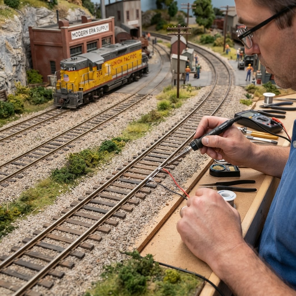
Learning how to solder track feeders is one of the most valuable skills you can develop as a model railroader. Whether you're building your first layout or expanding an existing one, reliable electrical connections are the foundation of smooth, consistent train operation. Without proper feeder wires soldered to your track, you'll likely encounter frustrating dead spots, flickering locomotives, and unpredictable performance that can quickly take the fun out of the hobby.
For beginners, the idea of soldering can feel intimidating. Hot irons, melting metal, and the fear of damaging expensive track sections are all common concerns. The good news is that soldering track feeders is a straightforward process once you understand the basics. With the right tools, a little practice, and the step-by-step guidance in this article, you'll be making clean, professional-quality solder joints in no time.
In this guide, we'll walk you through everything you need to know — from gathering your materials to testing your finished connections. By the end, you'll have the confidence to wire your entire layout with solid feeder connections that will keep your trains running reliably for years to come. If you're still in the early stages of planning your layout, you may also want to check out our guide on Choosing a Model Train Scale: The Ultimate Guide for Beginners before diving in.
What Are Track Feeders and Why Do They Matter?
Track feeders are short lengths of wire — typically 20 to 22 AWG — that connect your model railroad track directly to the main power bus that runs beneath your layout. Think of your bus wires as the electrical highway and your feeder wires as the on-ramps that deliver power to each individual section of track.
The Problem with Relying on Rail Joiners Alone
Many beginners assume that simply snapping track sections together with rail joiners is enough to carry electrical current throughout a layout. While this works in the short term for small, simple setups, rail joiners are mechanical connections — not electrical ones. Over time, they loosen, oxidize, and corrode, especially in layouts exposed to varying temperatures and humidity. The result is inconsistent power delivery and frustrating operational problems.
Soldered track feeders bypass this problem entirely by giving every section of track a direct, low-resistance electrical connection to your power source. This is especially critical if you're running a Digital Command Control (DCC) system, where clean, uninterrupted power delivery is essential for decoder communication. For more on DCC systems, check out our roundup of the 5 Best Starter DCC Controllers for New Model Railroad Hobbyists.
How Often Should You Add Feeders?
A general rule of thumb is to add a feeder pair (one for each rail) every three to six feet of track. On large layouts, this may mean dozens of feeder connections. On smaller layouts or simple ovals, you may only need a handful. The key is ensuring that no section of track is too far from a direct power connection.
Tools and Materials You'll Need
Before you start soldering, it's important to have the right equipment on hand. Trying to solder with the wrong tools is one of the most common reasons beginners struggle. For a broader overview of hobby tools, visit our guide on 10 Essential Tools for Model Railroading: The Ultimate Starter Toolkit.
Here's what you'll need specifically for soldering track feeders:
- Soldering iron — A 25 to 40-watt temperature-controlled iron is ideal. Avoid high-wattage irons over 60 watts, which can melt plastic ties and track bases.
- Solder — Use 60/40 rosin-core solder (60% tin, 40% lead) in a thin gauge, around 0.031 inches. Lead-free solder works but requires higher temperatures and more skill.
- Flux — Rosin flux paste helps solder flow cleanly and bond properly to the rail.
- Wire strippers — For preparing your feeder wires.
- Helping hands or tape — To hold the wire in place while you solder.
- Heat sink clips — Optional but helpful for protecting plastic components near the solder joint.
- Fine-grit sandpaper or a track cleaning block — To prep the rail surface before soldering.
- Feeder wire — 20 to 22 AWG stranded wire in two colors (typically red and black, or matching your bus wire color scheme).
You can find many of these items on our recommended products page, where we've curated quality options suited for model railroaders.
Preparing Your Track and Workspace
Good preparation makes the difference between a clean solder joint and a cold, unreliable one. Don't skip these steps.
Clean the Rail Surface
Solder will not adhere properly to dirty, oxidized, or oily rail surfaces. Before soldering, lightly sand the side of the rail where you plan to attach the feeder wire. A few strokes with fine-grit sandpaper or an abrasive track cleaning block will expose fresh, shiny metal. You can also use isopropyl alcohol on a cotton swab to wipe away residue. For ongoing track maintenance, our article on How to Clean Track Rails Effectively: The Ultimate Guide for Smooth Running Trains is an excellent resource.
Prepare Your Feeder Wires
Strip approximately 3/8 to 1/2 inch of insulation from the end of each feeder wire. Twist the exposed strands tightly together so they form a neat bundle. Then tin the wire by applying a small amount of solder to the stripped end before making the connection to the rail. This pre-tinning step makes the final joint much easier and faster to complete.
Set Up Your Work Area
Work on a heat-resistant surface and keep a damp sponge or brass wool tip cleaner nearby to keep your iron tip clean. A dirty tip dramatically reduces heat transfer and makes soldering much harder. Make sure the track is secured so it won't move while you work — even a small shift during soldering can result in a poor connection.
Step-by-Step: How to Solder Track Feeders
Now for the main event. Follow these steps carefully, especially on your first few attempts.
Step 1: Tin the Rail
Apply a small dab of flux paste to the side of the rail web (the vertical middle section of the rail). Touch your clean, hot soldering iron to the flux and then briefly touch the solder to the rail — not to the iron. The rail should be hot enough to melt the solder on contact. You're looking for a thin, shiny coating of solder on the rail surface. Work quickly; prolonged heat will warp plastic ties.
Step 2: Position the Feeder Wire
Hold the pre-tinned feeder wire against the freshly tinned rail. The two tinned surfaces should face each other. You can use a small piece of tape or a helping hands tool to hold the wire in place, or you can hold it with your non-dominant hand if you're comfortable doing so safely.
Step 3: Make the Joint
Touch your iron to the joint — contacting both the wire and the rail simultaneously. Within one to two seconds, the two tinned surfaces should flow together. Remove the iron immediately and hold the wire perfectly still for five to ten seconds while the joint cools and solidifies. Do not blow on the joint to cool it; this can cause a "cold solder joint" with poor conductivity.
Step 4: Inspect the Joint
A good solder joint is shiny and smooth, almost like a little volcano shape around the wire. A dull, grainy, or lumpy appearance indicates a cold joint, which means the connection may be unreliable. If you see a cold joint, reheat it briefly and allow it to re-flow and cool undisturbed.
Step 5: Repeat for the Opposite Rail
Remember — track feeders always come in pairs. Solder one wire to each rail, making sure to maintain consistent color coding (e.g., red to the right rail, black to the left rail when viewed from the front of the layout). Consistent polarity labeling will save you enormous headaches later, especially if you're running a DCC system. Speaking of which, proper feeder wiring is essential for getting the most out of your equipment — read our guide on the Best DCC Decoders for Locomotive Upgrades for more.
Step 6: Route and Connect to the Bus
Route your feeder wires down through a small hole drilled in your layout surface and connect them to the appropriate bus wires underneath. Twist the feeder to the bus wire and solder, or use a suitable connector. Keep feeder runs short — typically under 18 inches — to minimize voltage drop.
Common Mistakes to Avoid
Even experienced hobbyists occasionally run into problems with soldering. Here are the most frequent pitfalls beginners encounter:
- Using too much heat for too long. Apply heat quickly and efficiently. Lingering on plastic track with a hot iron will melt ties and warp the roadbed.
- Not cleaning the rail surface first. Solder simply will not bond to a dirty or oxidized surface. Always prep the rail.
- Skipping flux. Flux is what allows solder to flow cleanly. Don't skip it, especially on track work.
- Moving the wire before the joint cools. This is the primary cause of cold solder joints. Be patient.
- Using the wrong gauge wire. Wire that's too thin increases resistance; wire that's too thick is hard to handle and can stress the rail.
- Ignoring polarity. Inconsistent polarity labeling can cause short circuits, especially with DCC. Stay consistent.
Testing Your Feeder Connections
Once your feeders are soldered and connected to the bus, it's time to test before you close up the layout. Use a multimeter set to DC voltage to confirm that power is reaching the rail at the feeder location. With your DCC system or power pack on, you should see appropriate voltage at the rail.
Place a locomotive on the track and test for smooth operation in both directions. If the loco hesitates or stalls, check your solder joints for cold connections and verify your bus connections are secure. For advice on choosing the right DCC controller to power your layout, see our DCC Controller Review: Top 5 Picks for Precision Control and Best Value.
Frequently Asked Questions
What gauge wire should I use for track feeders?
For most HO, N, and O scale layouts, 20 to 22 AWG stranded wire is ideal for feeder wires. Stranded wire is more flexible than solid wire, making it easier to route through your layout. Your main bus wires should be heavier — typically 14 to 18 AWG — to handle the current load for the entire layout.
Can I solder track feeders to code 55 or code 40 N scale track?
Yes, but it requires extra care. Smaller rail profiles like Code 55 and Code 40 have less surface area and retain heat differently. Use a fine-tip iron, keep your contact time very brief, and use thinner solder. The technique is the same — it just demands a lighter touch. For N scale layout inspiration, see our article on the Top 10 Best N Scale Locomotives for Compact Layouts in 2024.
Do I need to solder feeders if I'm using a small, simple loop of track?
For a very small oval layout — such as a beginner or children's starter set — you may get away without feeder wires initially, relying on rail joiners. However, even small layouts benefit from at least one set of soldered feeders for reliability. If you're shopping for a beginner set, our guide on Best Model Train Sets for Kids: Top Picks for Beginners and Families has some great options.
What's the difference between resin-core solder and acid-core solder?
Always use rosin-core solder for electronics and model railroad work. Acid-core solder is intended for plumbing and will corrode your rails and wiring over time, causing exactly the kind of electrical problems you're trying to avoid. Look for solder labeled specifically for electronics or model railroad use.
How do I fix a solder joint that keeps failing?
Start by removing the old solder using a solder wick (desoldering braid) or a solder sucker. Clean the rail surface again thoroughly, re-apply flux, and redo the joint from scratch. Trying to reheat a badly failed joint without removing the old solder usually just makes things worse. Take your time and start fresh for a reliable result.
Conclusion
Mastering how to solder track feeders is a game-changer for your model railroad layout. With solid, direct electrical connections at regular intervals, you'll eliminate dead spots, reduce operational gremlins, and give your locomotives the clean, consistent power they need to perform at their best. It's a skill that takes a little practice to get right, but one that pays dividends every single time you run your trains.
Start small — practice on a scrap piece of track before tackling your main layout. Once you've made a few clean joints, the process becomes second nature. Before long, you'll be soldering feeders with confidence and enjoying a layout that runs exactly the way you imagined.
Ready to keep building your skills? Explore more of our guides on layout wiring, DCC setup, and track planning right here on Model Train Insider. Whether you're just getting started or fine-tuning an advanced layout, we've got the tips and resources to help you every step of the way. Check out our Best Starter DCC Controllers Reviewed article as a natural next step after getting your track wiring sorted.
Affiliate Disclosure: Some links in this article are affiliate links. We may earn a commission at no extra cost to you.
Enjoying this guide?
Browse our favorite recommended products.
James Mitchell
Model Train Enthusiast & Writer
James has been building layouts and collecting trains for over 15 years. He started Model Train Insider to help newcomers navigate the hobby with practical, no-nonsense advice drawn from hands-on experience.
Stay on Track
Get beginner guides, brand reviews, and layout tips delivered to your inbox. No spam—just trains.
Free forever. Unsubscribe anytime.
Related Articles
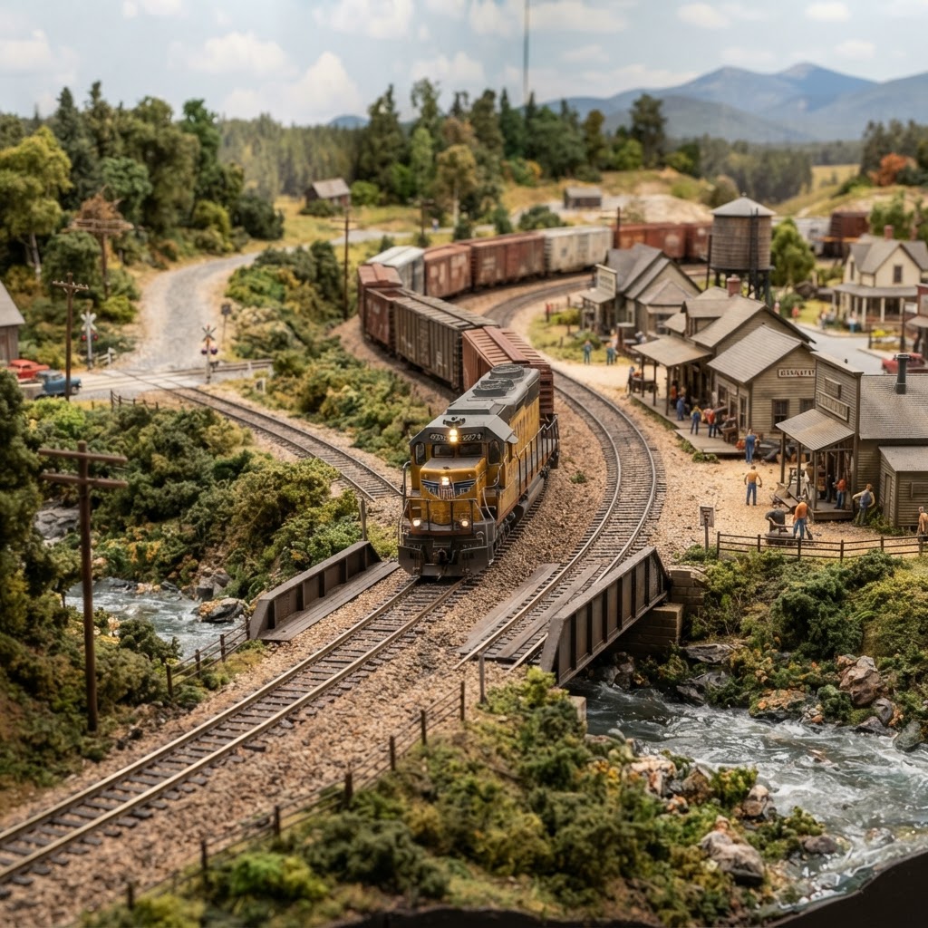
10 Best HO Scale Track Plans for Your Home Layout
Discover the 10 best HO scale track plans to transform your space. From compact switching layouts to grand mainlines, find the perfect design for your model train.
Read more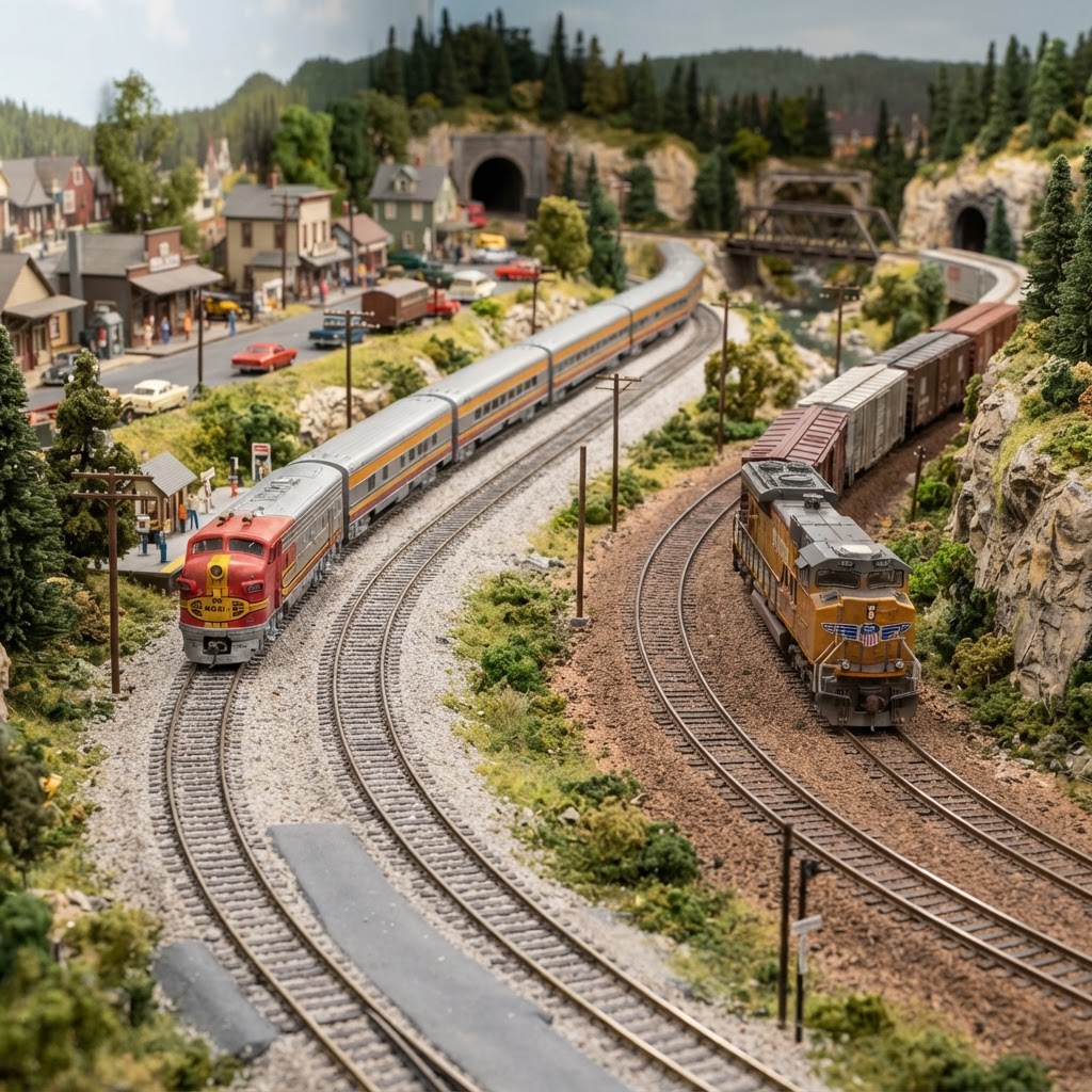
Kato Unitrack vs. Bachmann E-Z Track: The Ultimate Comparison for Modelers
Deciding between Kato Unitrack and Bachmann E-Z Track? We compare reliability, ease of use, and realism to help you choose the best track for your layout.
Read more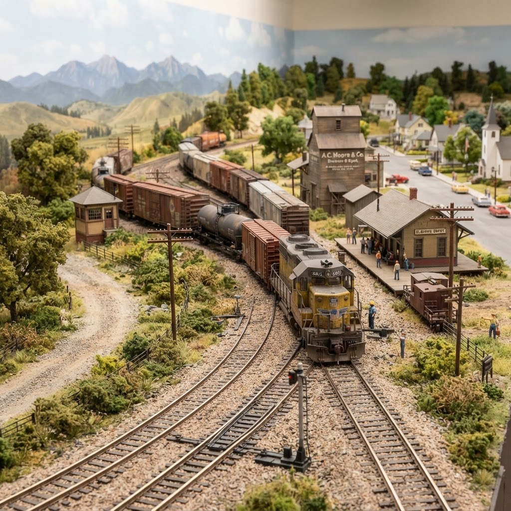
The Best HO Scale Track Options: A Guide to Building a Reliable Layout
Discover the best HO scale track options for your model railroad. Learn which brands offer the most reliability and realism for your dream layout design.
Read more